
Picture this: the ductwork shows up on site, the crew starts hanging it section by section, and then it hits a structural beam that wasn’t supposed to be there — or rather, was always there but nobody caught it. Now there’s a delay while someone figures out whether to reroute the duct, notch the beam (not happening), or drop the ceiling line lower than the architect wanted. Multiply that by a dozen similar surprises across a floor, and a straightforward mechanical installation turns into a scheduling headache with change orders attached.
This is exactly the kind of problem Building Information Modeling was built to catch before it happens. Instead of discovering conflicts with a tape measure and a frustrated foreman, coordinated 3D models let teams find and fix these issues on a screen, weeks or months before anyone picks up a duct section. For HVAC specifically, where routing has to weave around beams, pipes, cable trays, and ceilings all at once, this kind of upfront coordination isn’t a luxury — it’s what keeps the schedule intact.
What Is an HVAC Clash in a BIM Model?
In an HVAC clash, it means that the ducting has encroached on the same area where it is not supposed to be located. Not all HVAC clashes are created equal and it is best to understand the differences between these clashes.
A physical clash is one that’s easy to spot: the duct is physically clashing with a beam, a pipe, or equipment. When two things try to exist in the same space at the same time.
A clearance clash is subtler. The duct might not touch anything, but it doesn’t leave enough room for insulation, access panels, or a technician to service a damper. Nothing overlaps in the model, but nothing would actually fit on site either.
Then there are soft or workflow clashes — situations where the duct technically fits, but the routing creates a maintenance nightmare, blocks access to equipment, or ignores the sequence in which trades need to install their systems. These rarely show up in a basic geometry check, which is why relying only on automated detection isn’t enough.
How to Identify HVAC Clashes
The identification process starts by bringing every discipline’s model into one place — architectural, structural, HVAC, plumbing, electrical, fire protection, whatever applies to the project. Each team works in its own model, but coordination only works once those models are combined into a single federated model that everyone can view together.
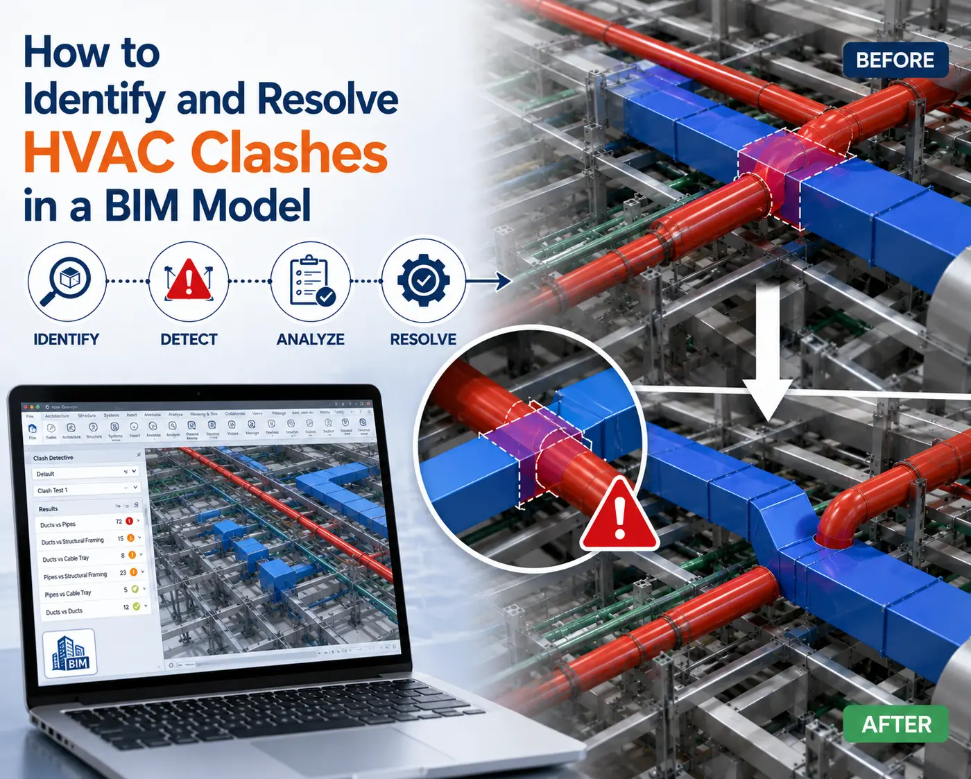
From there, the HVAC routing gets reviewed against everything around it. This is where 3D Clash Coordination comes in: running automated clash detection software that scans the federated model and flags every point of intersection between selected elements. It’s fast, and it catches the hard clashes reliably.
But automated detection has blind spots. It won’t tell you that a duct technically clears a beam by two inches but leaves no room for the required insulation wrap. It won’t flag that a valve needs three feet of clearance to open properly. That’s why visual, model-based walkthroughs still matter — someone with field experience looking at the routing and asking, “Would this actually work if I were building it?”
The Role of Structural BIM Modeling in HVAC Coordination
HVAC coordination can’t happen in isolation from the structure, because the structure isn’t going anywhere. Beams, columns, slabs, and load-bearing walls are fixed points that duct routing has to work around — not the other way around.
This is precisely what the structural BIM modeling helps to do. Through the creation of a precise structural model, a coordinator will know exact locations of the beams and their depth, interruptions of corridors by the columns, and openings provided within the slabs. Consequently, the decision on whether it is necessary to move the duct or provide a structural opening may be made.
Without an accurate structural model, HVAC teams are essentially guessing at what’s above the ceiling — and guessing is how beams end up getting field-cut, which nobody wants.
How to Resolve HVAC Clashes
Finding a clash is the easy part. Resolving it well is where the real coordination work happens. Common fixes include:
- Adjusting duct elevation to clear a beam or pipe
- Rerouting the duct entirely around an obstruction
- Coordinating service elevations with electrical and plumbing so everything stacks logically
- Modifying duct dimensions, where the design allows some flexibility
- Coordinating a structural opening with the structural engineer, rather than rerouting
- Preserving required clearances for insulation, access, and code compliance
- Protecting maintenance zones around equipment like AHUs, VAV boxes, and dampers
The goal isn’t just to make the red clash marker disappear in the software. A “resolved” clash still has to be buildable in the field, accessible for future maintenance, and compliant with project specs and code. A fix that looks clean in the model but leaves no room for a technician to reach a filter isn’t really a fix.
Common HVAC Clashes and Resolutions
| Common HVAC Clash | Typical Cause | Possible Resolution |
| Duct vs. structural beam | Routing crosses beam line | Adjust elevation or reroute around beam |
| Duct vs. cable tray | Multiple services compete for the same zone | Coordinate service elevations, establish stacking order |
| Duct vs. pipe | MEP systems overlap in tight ceiling space | Reroute one system or set a service hierarchy |
| Duct vs. ceiling | Insufficient plenum space | Resize duct, adjust elevation, or revisit ceiling height |
| Duct vs. equipment | Routing blocks access or maintenance clearance | Reposition duct while preserving access zone |
| Duct vs. structural column | Corridor width limits routing options | Split duct run or shift alignment around column |
Why Clash Resolution Is an Iterative Process
Here’s the part that catches new coordinators off guard: fixing one clash almost always creates the possibility of another. Move a duct up six inches to clear a beam, and now it’s crowding a cable tray that was fine before. That’s not a failure of the process — it’s just how coordination works in a tightly packed ceiling space.
The practical workflow looks like this:

Every time a significant change gets made, the model needs to be re-run through clash detection. Skipping that step is how a “fixed” clash quietly reintroduces a new one that nobody catches until the model is signed off.
Practical Example
Consider a scenario where the ductwork is first laid in such a way that it goes directly through the Structural Beam. In a 3D clash detection exercise, the software automatically picks out this problem. Rather than waiting till later for the field people to come across this issue, the BIM group gets the structural model, reviews the beam thickness, and finds that the duct is okay to move three inches down without any impact on the ceiling layout. Then they modify the height and check whether the change causes a clash with a cable tray that was present near the duct.
Conclusion
HVAC clash resolution isn’t really about hunting down red marks in a clash report — it’s about building a system that will actually work once it leaves the screen and hits the job site. Building Information Modeling gives teams a shared, accurate picture of the building; 3D Clash Coordination surfaces the conflicts early; and Structural BIM Modeling makes sure HVAC routing respects the fixed realities of beams, columns, and slabs. Combined, they turn what used to be a site-discovered problem into a design-phase decision — one made with time, information, and options, instead of a stalled crew and an expensive change order.