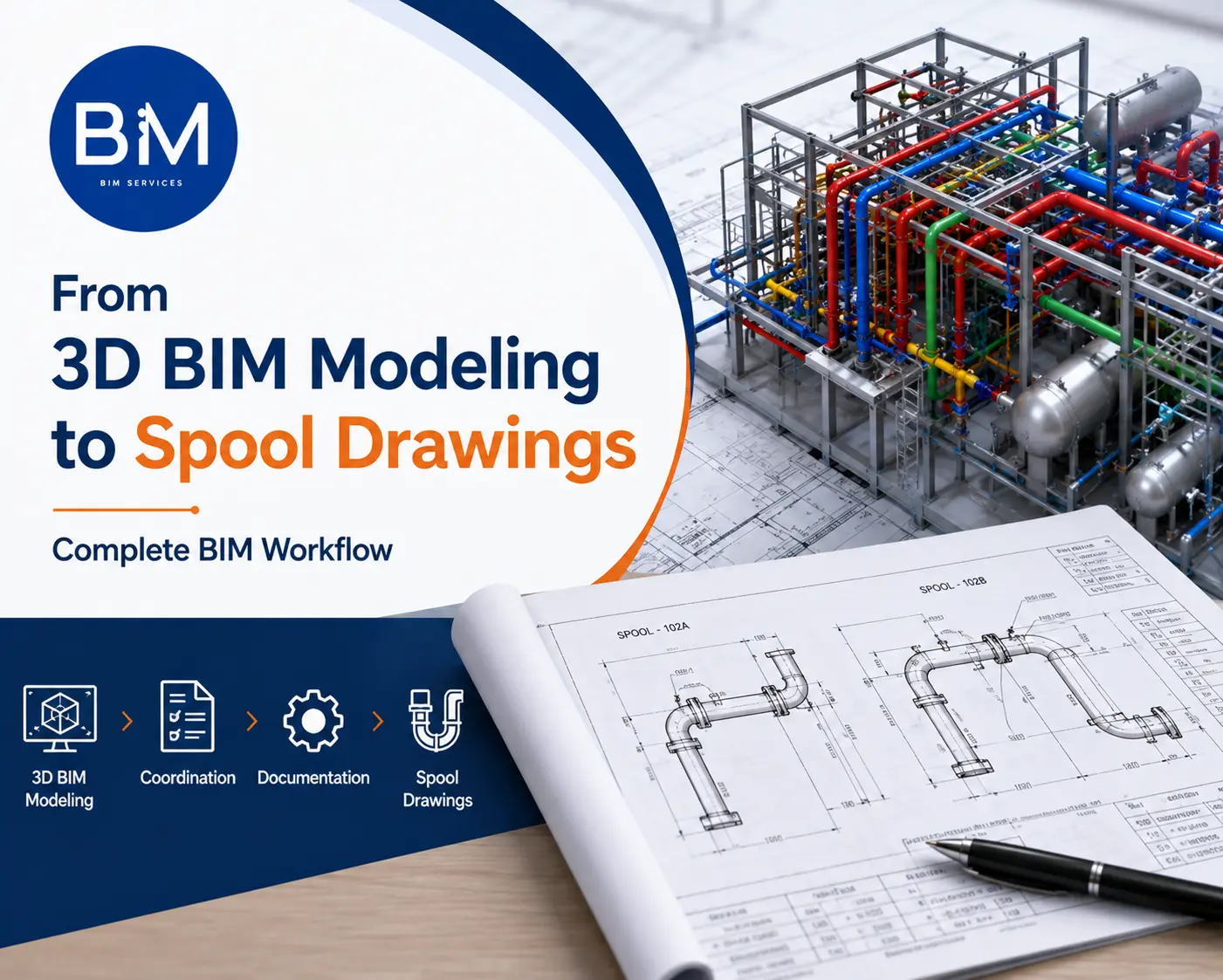
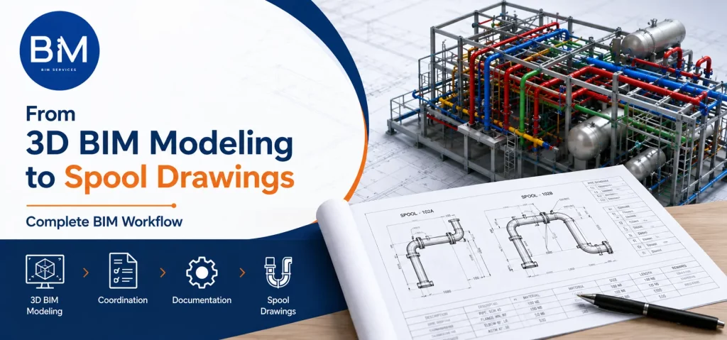
The question as to how a digital model becomes the precise pipe segments that an assembly company then fabricates and welds is really the same question of how one of the most applied aspects of Building Information Modeling works. The process of converting the coordinated 3D model into a spool drawing is quite a logical progression. Let us see how it happens step-by-step.
What Is 3D BIM Modeling?
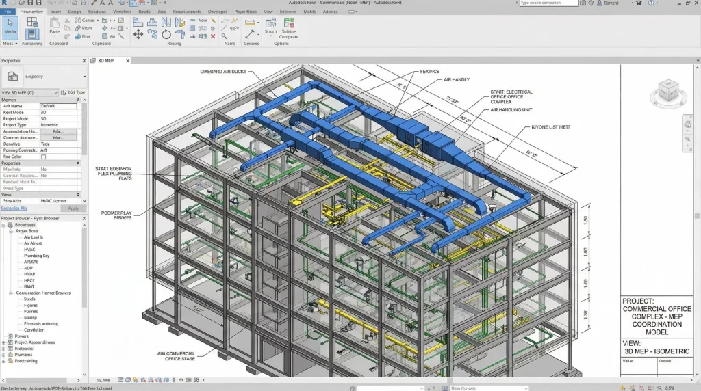
Fundamentally, 3D BIM Modeling entails creating a digital, data-laden model of the systems of the facility. Unlike a plain 3D model, a BIM Model contains details of materials, dimensions, links, and associations between various elements. It is for this reason that BIM Modeling proves so useful compared to conventional drafting
In this phase, various disciplines are built in a combined model. Structures create the frame of the building. HVAC ducts, plumbing pipes, electrical conduits, and fire protection are all modeled according to engineering intent.
In cases where renovations or retrofits have to be carried out, the solution used by most professionals is called Laser Scan to BIM. Through the use of a laser scanner, millions of data points from the structure will be captured to create what is known as a point cloud, which is then used to create a 3D BIM model.
Project BIM Coordination
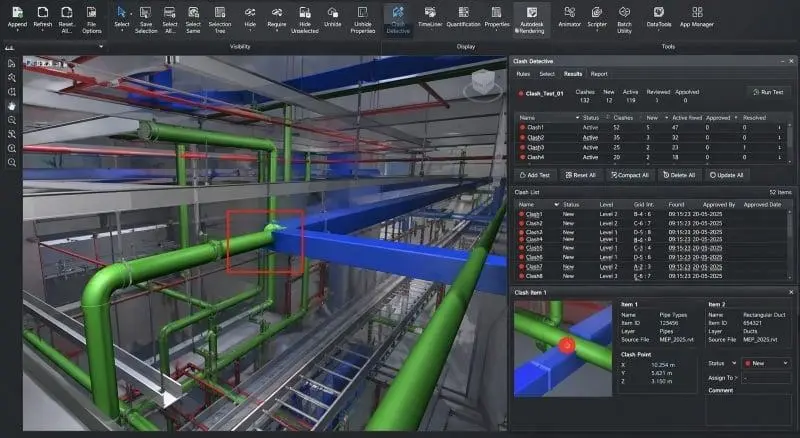
Once individual discipline models are ready, they don’t just get bundled together and called finished. They go through Project BIM Coordination, a structured process that catches problems before they become expensive field issues.
Here’s what that involves:
- Model Federation brings all discipline models — architectural, structural, MEP — into a single combined environment so everyone can see how systems interact spatially.
- Model Review follows, where coordinators check each model against project standards, spatial requirements, and design intent.
- Clash Detection is where software scans the federated model to identify physical conflicts, like a duct running straight through a structural beam or a pipe intersecting an electrical tray.
- Clash Resolution happens next. The teams not only identify but resolve issues, modifying the layout of routes, elevations, or components until the systems work properly without any clashes. Again, it is to be reiterated that Clash Detection and Clash Resolution are not standalone workflow stages but are both components of Project BIM Coordination.
- Then, a Constructability Review is carried out to determine whether the model is buildable under real-world conditions.
Coordination Meetings take place at each stage where the architect, engineer, and trade contractors meet to resolve any outstanding issues. Based on these meetings, model updates are made, and the process continues until all parties sign off.
The result is a Final Coordinated Model — a single source of truth that everyone trusts moving forward.
LOD 400: Fabrication-Level BIM Modeling
With coordination complete, the model moves into LOD 400, often called fabrication-level or Fabrication Modeling. This is where the model stops being a design representation and becomes a construction tool.
At LOD 400, generic pipe runs are replaced with actual fittings, valves, flanges, hangers, and supports. Every weld location gets defined. Exact dimensions, connection types, and installation details are added so the model reflects precisely what will be fabricated and installed, not just what was designed.
This level of detail is what separates conceptual BIM Modeling from a model that can actually drive a fabrication shop’s work.
Spool Segmentation
A piping system might stretch hundreds of feet, but it’s not possible to build, ship, and install a single stretch in one go. This is where spool segmentation fits into the picture.
LOD 400 model is segmented into spools based on limitations such as shipping size, crane capacity, welding access, and installation sequence. Each spool has an identification number that connects it to its exact location within the model as well as the installation schedule. It is the numbering of each spool that makes it possible to manage large projects when many separate parts begin moving around in the process of fabrication.
Spool Drawing Generation
Once spools are segmented, the model generates Spool Drawings — the actual documents fabricators use on the shop floor.
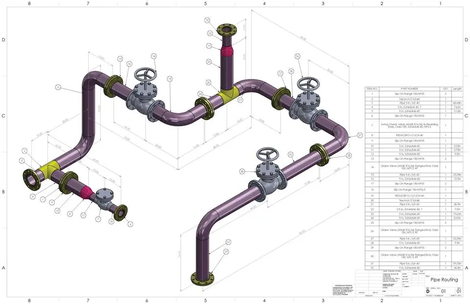
A well-prepared spool drawing typically includes an isometric view showing the spool’s exact shape and orientation, along with precise dimensions and pipe lengths. It specifies pipe sizes, marks every weld location, and details each fitting used.
Material callouts confirm exactly what’s needed, supported by a Bill of Materials (BOM) listing every component, quantity, and specification. Fabrication notes round things out, covering special instructions like coating requirements or tolerance allowances.
Together, these elements turn a digital model into a self-contained, buildable instruction set.
How Spool Drawings Improve Fabrication
Spool drawings aren’t just paperwork; they directly improve how projects get built.
Fabrication shops work faster because there’s no guesswork involved. Material planning becomes more accurate since BOMs are generated straight from the coordinated model. The quality control process becomes better as inspectors can check their work based on the exact specifications rather than estimates.
On site, precise spool drawings allow for fast installation, as workers will be aware of how each component should fit into the whole scheme. This will decrease errors, which usually lead to expensive reworking, and will improve overall efficiency of the process.
Bringing It All Together
The path from 3D BIM Modeling to spool drawings shows how Building Information Modeling turns coordinated digital design into real, buildable components. Through careful Project BIM Coordination, detailed LOD 400 fabrication modeling, and precise spool segmentation, a complex system of pipes and fittings becomes a set of clear, accurate spool drawings.
For teams offering MEPF BIM Services, this workflow is what separates guesswork from precision. When BIM Services are applied consistently from modeling through fabrication, the payoff is fewer clashes, less rework, faster installation, and construction projects that run the way they were designed to.