
HVAC schematic drawings reveal the overall workings of a building’s heating, ventilation, and air conditioning systems in a coherent manner, without being specific about its dimensions or height of ceilings. These diagrams are similar to electrical diagrams because they explain how the equipment and control devices are related to each other, along with the flow of air, water, or refrigerant through the system. They help engineers determine whether the design concept is correct and assist contractors in understanding the system installation process. Because every trade eventually shares the same ceilings and shafts, these diagrams also become the starting reference for MEPF drawing coordination.
What Do HVAC Schematic Drawings Show?
A typical set covers the central equipment, the distribution network and the controls that tie them together. Standard symbols and flow arrows show, for example, an air handling unit connected to a chiller loop, a VAV box serving each zone, or a boiler feeding a hydronic circuit. What surprises many newcomers is how much is left out, because HVAC schematic drawings rarely show wall locations, exact duct routes or structural grids. Their job is to explain function rather than geometry, so tags, capacities and set points sit beside each item and the design intent can be checked at a glance. The table below summarizes the main components and what each one does.
| Component | Role on the drawing | Typical example |
|---|---|---|
| Air handling unit (AHU) | Conditions and circulates supply air | Rooftop unit serving one floor |
| Chiller or boiler | Produces chilled or hot water | Plant room equipment |
| Pumps and piping loops | Move water between plant and coils | Primary and secondary chilled water loops |
| VAV boxes and terminal units | Regulate airflow to each zone | One box per office zone |
| Ducts and dampers | Carry and balance air | Supply, return and exhaust mains |
| Controls and sensors | Link thermostats, valves and fans in sequence | Duct static pressure sensor |
Coordinating with Architectural and Structural Designs
Architectural Drafting Services supply the floor plans, ceiling heights and room layouts that tell the mechanical team where equipment can actually go. While a schematic might need the installation of a fan coil unit in every classroom, it is the architectural drawing that determines if the ceiling void will be able to accommodate it. The third drawing type that is required is the structural drawing because the placement of ductwork and piping is dependent on the presence of beams, slabs, and columns. Catching conflicts like this early keeps the system logic intact while only the routing changes, which is exactly why well-maintained HVAC schematic drawings save time later.
Types of HVAC Schematic Drawings and How They Differ from Layout Drawings
Several kinds of schematics exist, and each answers a different question. Air-side diagrams follow the supply, return and exhaust path, water-side diagrams trace chilled water, hot water or condenser loops, and refrigerant diagrams cover piping for VRF or split systems. Control schematics, often paired with a sequence of operation, show how fans, valves and dampers respond to sensors, and all of them belong to the wider family of HVAC schematic drawings. HVAC layout drawings are a different animal: they are scaled plan views showing where ducts, diffusers and equipment physically sit, with sizes and elevations. In short, the schematic explains how the system behaves, while the layout shows where it goes, and a project needs both before fabrication begins.
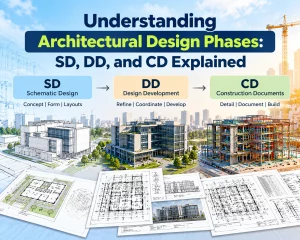
Also Read: Understanding Architectural Design Phases: SD, DD, and CD Explained
How HVAC Schematic Drawings Are Prepared
HVAC schematic drawings begin with load calculations and the design brief, which tell the engineer how much heating and cooling each zone needs. From there the designer selects equipment, sketches the system flow in CAD or Revit, and assigns tags, capacities and control points. The draft is reviewed against the architectural plans and the mechanical specification before it is issued for coordination. Once layout drawings and a 3D model are developed from the schematic, the team can federate the discipline models in Navisworks or a similar tool. A check at this stage might reveal a duct crossing a sprinkler main or a chilled water pipe hitting a beam, so the issue gets fixed in the model instead of on site, which is the main value of BIM Clash Detection.
How LOD Stages Influence HVAC Drawing Development
Level of Development, or LOD, describes how much reliable information a model element carries, and it grows as the design matures. At LOD 100 and 200 the mechanical system is mostly conceptual, with approximate equipment sizes and generic duct allowances. Early HVAC schematic drawings are therefore based on load schedules and flow logic rather than final manufacturer data. By LOD 300 and 350, ducts, pipes and equipment have real sizes, connections and clearances, which is the level most trades use for coordination. LOD 400 adds fabrication detail such as hangers, flanges and spool breaks, and the schematic is updated so it still matches what will be installed.
Benefits of Accurate HVAC Schematic Drawings
Structural Drafting Services supply the framing, openings and slab details that mechanical designers need when they pass ducts and risers through a building. When those details match the schematic, contractors order the right equipment, subcontractors price with fewer assumptions and RFIs decrease. Engineers gain faster design reviews because the system logic is easy to follow. Owners and facility managers benefit as well, since a clear schematic becomes the reference for commissioning, maintenance and later retrofits. In practice, a project with consistent, well-checked HVAC schematic drawings tends to see fewer site changes, smoother approvals and a cleaner handover.
Conclusion
HVAC schematic drawings explain how a building’s mechanical system is meant to behave, long before a single duct is hung. They connect equipment, controls and airflow to the architectural and structural drawings, and they give coordination teams a clear reference when conflicts appear. Used well, they reduce rework, support better decisions on site and leave owners with documentation they can actually use. Whether the project is a small school or a large hospital, keeping these drawings accurate and updating them with each LOD Progression keeps every trade working from the same information.