BIM for Modular Construction connects design intent, factory production, and site assembly through one coordinated model. Modular construction builds complete or partial building units, called modules, in a controlled factory, then transports them to site, where they are lifted, connected, and finished. Because most of the work happens off site, an error found after fabrication is costly, and a finished module cannot be trimmed to fit its neighbour the way a conventional frame can. A shared model lets architects, structural engineers, MEP designers, and the manufacturer settle dimensions, services, and connections before steel is cut or pipework is assembled. Every later decision, from factory sequencing to crane planning, depends on the accuracy of the underlying 3D BIM Modeling.
BIM for Modular Construction: Types of Modules and Modeling Requirements
Not every module is modeled the same way, because the detail required depends on what the factory has to build and how each unit will be transported, lifted, and connected. Most projects combine several systems, and BIM for Modular Construction works best when each type is modeled to match its production method. The table below summarizes the main differences, and the approach should be confirmed with the manufacturer before modeling starts, since production methods vary between factories.
Modeling Requirements by Module Type
| Module Type | What Is Modeled | Key Requirement |
|---|---|---|
| Volumetric modules | Complete unit with structure, finishes, MEP, and openings | Transport envelope and neighbour interfaces |
| Panelized systems | Wall, floor, and roof panels with framing and openings | Panel joints and assembly sequence |
| Structural modules | Frames, beams, columns, bracing, and connection plates | Connection geometry and load path |
| MEP modules | Ducts, pipes, trays, supports, and equipment | Service access and connection points |
| Bathroom and utility pods | Fixtures, wall and floor build-up, drainage, and services | Fixed service positions and repeatable accuracy |
Key Considerations in Modular BIM Modeling
Structural Modeling for modular projects must capture connection plates, bolts, welds, and tolerances that conventional models often leave to a later detailing stage. Module-to-module interfaces come next: every shared wall, floor, and ceiling needs agreed boundaries, so no element is modeled twice or left as a gap between units. Design for Manufacturing and Assembly (DfMA) shapes these choices by keeping components repeatable and sequences practical for the production line. MEPF routes need service access, so valves, shafts, and connection points remain reachable once modules are joined. Transport limits, lifting points, and unit weights belong in the model early, and manufacturing tolerances should be written into it so small factory variations do not accumulate into site problems, particularly where several modules stack or sit side by side. Treating these items as modeling rules is the core of BIM for Modular Construction.
BIM for Modular Construction: Workflow from Design to Installation
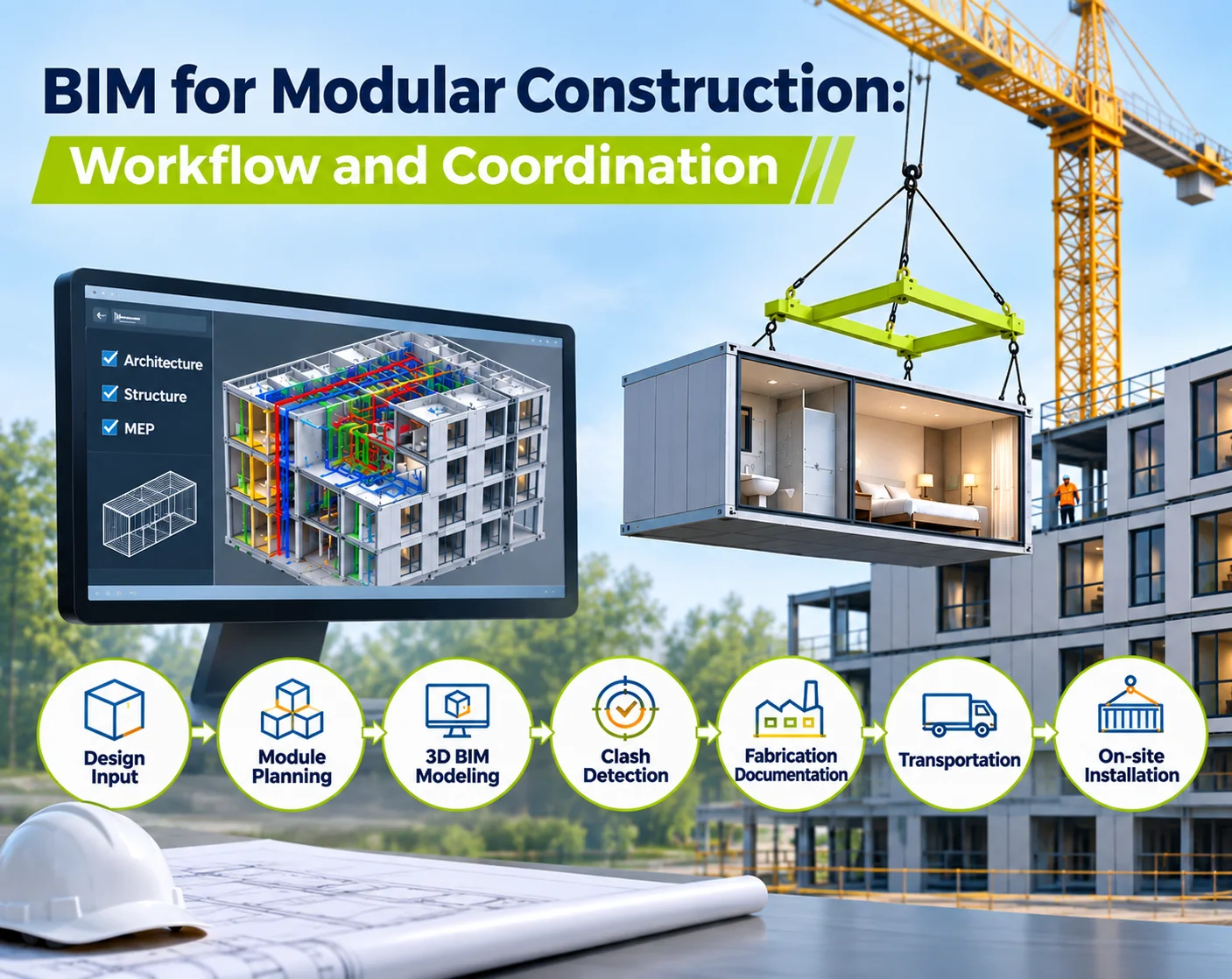
The workflow begins with design inputs such as architectural intent, structural loads, services strategy, factory limits, and transport routes, followed by a module breakdown that fixes sizes, grid positions, and interface zones. Discipline models are then built through detailed 3D modeling for each module type. Applying BIM for Modular Construction at this point means architectural, structural, and MEP coordination resolves every connection and penetration in the model rather than at the factory. Model validation and clash detection confirm the coordinated model is ready, after which fabrication drawings and documentation go to production. Finally, transportation and on-site installation sequences are checked against lifting, crane access, and site delivery constraints, so the assembly order has already been tested when the first module arrives.
Also Read: Understanding Architectural Design Phases: SD, DD, and CD Explained
Coordination Challenges in Modular Construction Projects
BIM for Modular Construction exposes coordination problems while they are still inexpensive to fix. Structural connection misalignment, module dimension discrepancies, and insufficient installation clearances are typical: a connection plate slightly out of position can stop two modules from closing. MEP service conflicts and incorrect openings or penetrations appear where ducts, pipes, and cable trays cross module boundaries or pass through structural members. Transportation and lifting constraints, such as height limits and lifting-point locations, can also be tested against the model before fabrication. Federated model reviews flag these issues early, and each fix is recorded as a model revision. Reviewing issues module by module also gives the manufacturer a clear list of what changed and why. Running systematic BIM Clash Detection across every discipline turns these checks into corrections made before fabrication.
BIM for Modular Construction: Deliverables and Quality Checks
A modular package normally includes coordinated 3D BIM models, module layout drawings, shop and fabrication drawings, structural connection details, MEP coordination drawings, material schedules, and installation documentation, with fabrication drawings carrying enough dimensional and assembly detail for the factory to build without guesswork. How these are checked matters as much as the drawings themselves, and BIM for Modular Construction depends on release rules agreed at the start. Before a model goes to fabrication, the team should confirm module dimensions against the transport envelope, verify that connections and penetrations match the structural design, check service clearances, reconcile schedules with model quantities, apply consistent module IDs, confirm that the model, drawings, and schedules all reference the same revision, and close or formally accept every open clash.
Practical Applications of BIM in Modular Construction
HVAC BIM Coordination Services are often where modular teams see value first, because ducts and risers must align from one module to the next. Consider an illustrative modular hotel, not a completed project, with repeated guest-room modules. A typical room is modeled once with its structure, finishes, bathroom pod, and services, then reused across floors with controlled variations for accessible rooms and end-of-corridor units, which keeps repeated production efficient without hiding the exceptions. Room-level ductwork, plumbing, and electrical connections are coordinated with corridor and riser routes through project BIM coordination, and module connections are validated by checking bolt positions, gaps, and lifting points between stacked units. Fabrication documentation then gives the factory clear drawings and gives the site crew a numbered installation sequence. That chain from room model to site sequence is how BIM for Modular Construction.
Conclusion
Modular projects reward teams that settle design decisions early, and a coordinated model is what makes that possible. Used this way, the model becomes a working reference for designers, the factory, and the site crew rather than a record produced after decisions are made. Define module types, interfaces, and release checks at the outset, then keep the model aligned with factory and site feedback. From concept to installation, a clear plan for LOD Progression keeps modules buildable, transportable, and ready for assembly.