Step into any contemporary commercial building, and you can see systems working behind the scenes around you—the ductwork transporting the conditioned air, pipes transporting water, and cables supplying power. This doesn’t cross most peoples’ minds. However, for the design teams trying to integrate these systems, it is one of the biggest challenges of their profession.
That’s precisely what HVAC duct routing is all about. And that’s precisely why many contractors and engineers have turned to BIM for planning such work. If done right, BIM will help with HVAC duct routing by discovering issues via computer rather than on the ground.
Now let’s examine what duct routing entails, why it has always been such an issue, and how Building Information Modeling has turned the tables.
What Is HVAC Duct Routing?
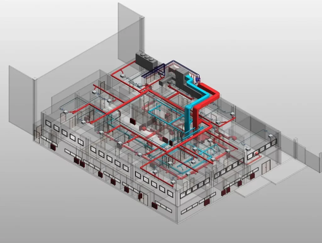
HVAC duct routing is the simple task of defining the route through which air ducts travel in a building. Air ducts have to travel from mechanical rooms all the way to any location requiring heating, cooling, and ventilation.
Not only is it an issue of putting lines on a ceiling plan; good ductwork will improve air movement, energy efficiency, noise level, and occupant comfort within the room. If ductwork is routed badly, this could result in poor air movement in one area of an office while the system works double-time to make up for it.
It becomes even more complicated based on what kind of building it is. Hospitals have to meet certain standards of pressure and air filtration. Warehouses need to have their ductwork run for long distances through large open spaces. High rises will require ductwork to run through tight risers from floor to floor.
Why Traditional HVAC Duct Routing Creates Problems
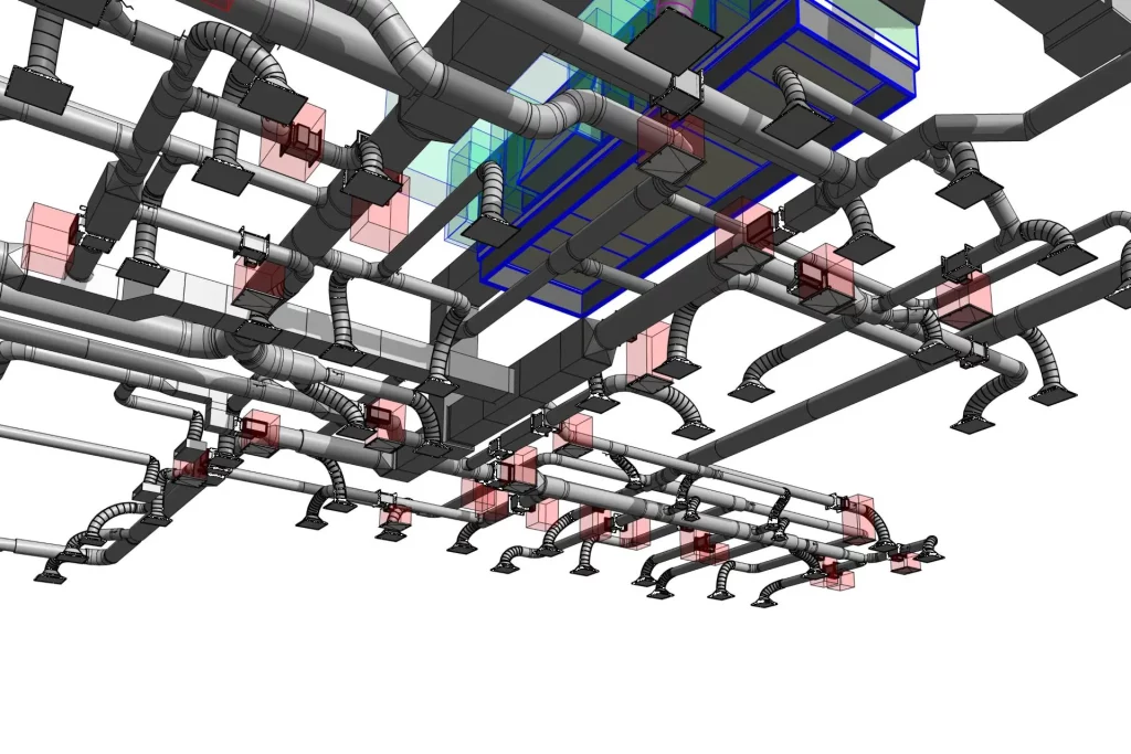
Before BIM became standard practice, duct routing relied heavily on 2D drawings and a good deal of guesswork. Engineers would lay out ductwork on one drawing, while structural engineers worked on another, and electrical or plumbing teams worked on theirs. Nobody could easily see how all these systems overlapped until construction was already underway.
This created some familiar headaches:
- Ceiling spaces are never as generous as they look on paper, and ducts often have to compete for the same few inches of room.
- Structural beams would show up right where a duct needed to pass.
- Plumbing lines, electrical conduit, and fire sprinkler piping would collide with mechanical routing in ways nobody caught until the crew got on site.
- Redesigns, cut material, and rebuilt sections added cost and delay after installation had already begun.
When that happens, work stops. Someone has to redesign the route, cut material, or rebuild sections that were already installed. That means wasted material, blown schedules, and costs that creep up fast. Sound familiar? If you’ve worked on more than a couple of projects, it probably does.
How BIM Improves HVAC Duct Routing
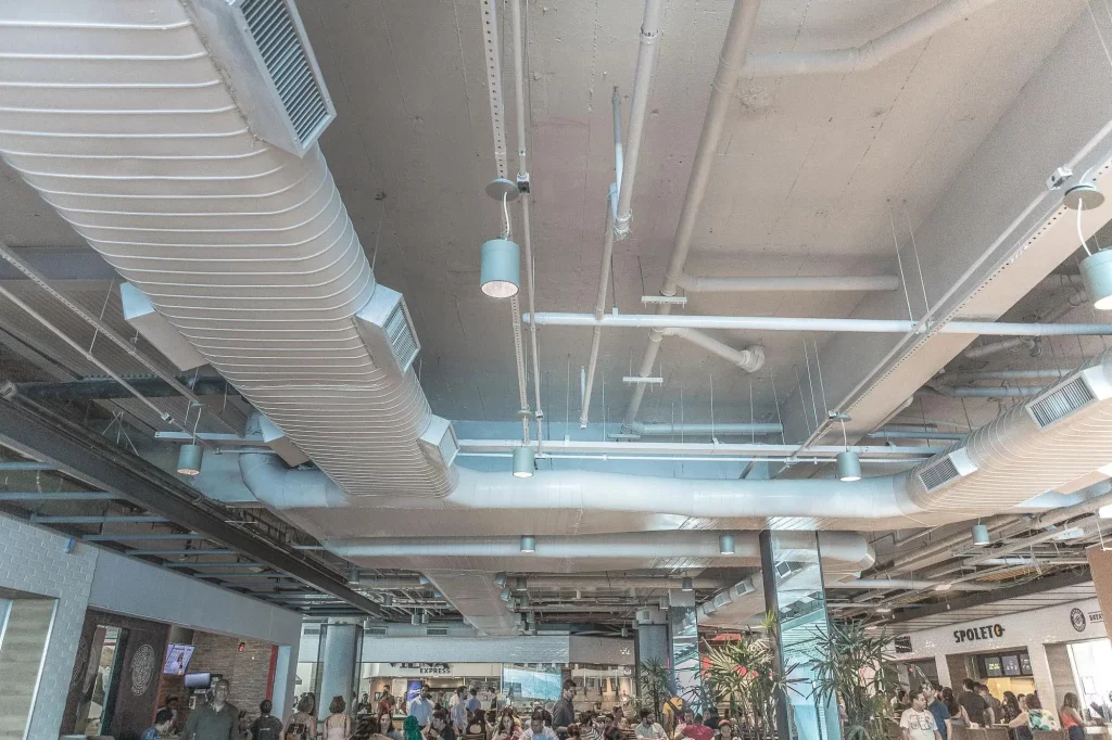
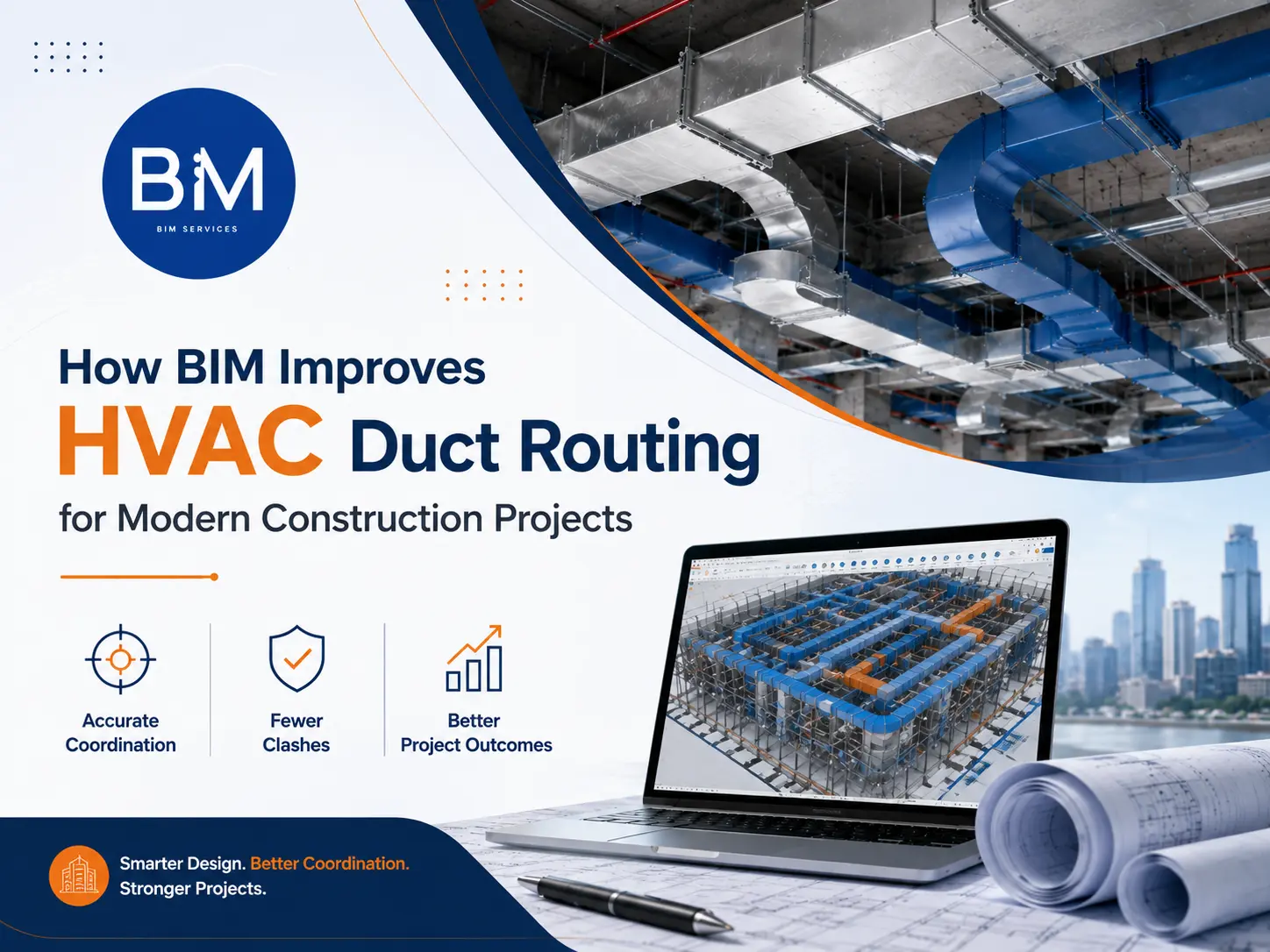
This is where 3D BIM modeling earns its keep. Instead of separate drawings for separate trades, everyone works from one coordinated digital model. Here’s how that changes duct routing in practice.
- Better 3D Visualization: The advantage of 3D BIM modeling is that engineers will be able to visualize how the ducts are integrated into the whole building design along with the beams, pipes, ceiling and other equipment. They do not have to think about it but just visualize it.
- Clash Detection Before Installation: This is possibly the most significant benefit of BIM for MEP coordination. The program highlights any clash between the ductwork and either the structure or the architecture. It does this well before the actual construction commences. You would not need to have your work blocked by an unexpected beam while you are in the middle of construction.
- Improved Space Optimization: Ceiling voids are tight, and every trade wants a piece of that space. BIM helps teams sequence ducts, pipes, and cable trays efficiently while still leaving room for maintenance access later. Nobody wants a duct routed so tightly that a technician can’t service the damper five years down the road.
- Better Collaboration: Because everyone—architects, structural engineers, MEP teams—works from a shared model, communication improves naturally. Questions get answered faster. Fewer assumptions get made. Design revisions happen through discussion instead of guesswork.
- Faster Design Changes: Buildings evolve during design, and structural changes happen. With BIM, rerouting ducts around a new beam or revised ceiling height is a digital update, not a redesign from scratch.
- Accurate Material Quantities: BIM models generate duct lengths, fittings, and insulation quantities automatically. That means fewer estimation errors, tighter procurement, and less material sitting unused on site.
- Support for Prefabrication: Perhaps most valuable for today’s labor-conscious job sites: fabrication teams can build duct sections directly from the BIM model. This improves fit accuracy and shifts labor from the field to the shop, where conditions are more controlled.
Benefits of Using BIM Services for HVAC Projects
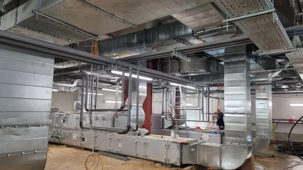
Bringing in professional BIM Services isn’t just about software—it’s about experienced coordination. Teams using proper BIM Services typically see improved coordination between trades, reduced rework, and fewer costly surprises mid-construction. Installation moves faster because conflicts get resolved digitally. Design accuracy improves because every discipline is checking against the same model. And communication across the project team becomes far more straightforward.
Real-World Scenario
Think about a medium-sized commercial office building project. While the building is under construction, the big supply duct that is going through the ceiling of the second floor ends up hitting a load-bearing beam directly. Without the use of BIM, this problem comes to light at the job site.
In the presence of BIM technology, this conflict emerges in the process of coordination of design. It involves changing the course of the duct using software, and then comparing the model with the structural and architectural models, thus solving the conflict within an afternoon’s time instead of wasting days at the construction site. This saves money in labor, materials, and further time for other contractors.
Comparison: Traditional vs. BIM-Based HVAC Design
| Traditional HVAC Design | BIM-Based HVAC Design |
| 2D Drawings | Intelligent 3D BIM Modeling |
| Manual coordination | Shared BIM model |
| Clashes discovered onsite | Clashes detected before construction |
| Frequent rework | Minimal rework |
| Longer installation | Faster installation |
| Manual quantity estimation | Automated quantity takeoffs |
| Higher material waste | Optimized material usage |
| Difficult revisions | Faster digital updates |
Conclusion
In today’s construction projects, BIM is used for HVAC duct routing as it addresses actual issues which previously were simply part of the work. The clashes can be discovered early. The ceiling space is utilized effectively. People collaborate with the help of one model, not trying to guess what others have in mind.
Overall, BIM brings the process of HVAC duct routing to another level and makes it predictable, coordinated, and transparent. For constructors, engineers, and clients who wish to save time and money on rework and do not want to delay the schedule, there is no need to search for more effective solutions than using BIM Services and 3D BIM Modeling.