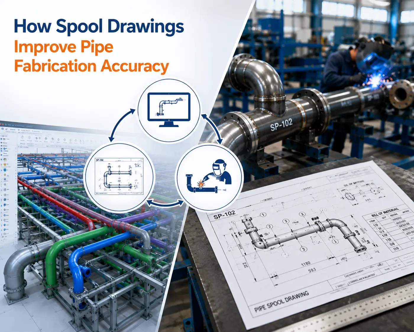
Pipe Fabrication Accuracy starts long before a pipe reaches the jobsite. A pipefitter cuts a pipe to size from the drawing and then welds it. At startup, it is found that the branch fitting is installed in the wrong position and the flange cannot be aligned with the pump nozzle. Now there’s a cut-out, a re-weld, and a schedule delay nobody budgeted for. Anyone who’s spent time around a piping job has seen some version of this — a wrong pipe length, a fitting rotated a few degrees off, or a connection point that doesn’t match the equipment, turning a simple install into a half-day of rework.
This is the gap spool drawings close, turning a piping system into something a shop and field crew can build from, with dimensions, orientations, and connection points pulled from a coordinated model instead of a rough sketch.
What Is a Spool Drawing?
A spool drawing is a fabrication-level drawing of one section, or “spool,” of a larger piping system. Instead of showing an entire mechanical room or riser on one crowded sheet, the run is broken into smaller segments a shop can fabricate, tag, ship, and install as a single unit.
Each spool drawing typically includes:
- Pipe dimensions and cut lengths
- Fittings, elbows, and reducers
- Flange types and locations
- Valve placement
- Weld locations and joint types
- Connection points to adjoining spools or equipment
- Material specifications
- Component and spool identification numbers
None of this is invented on the spot — it comes from a coordinated BIM model, already routed, sized, and checked against everything else in the building. A spool drawing is that 3D BIM modeling work translated into a document a fabricator can act on.
How Spool Drawings Improve Pipe Fabrication Accuracy
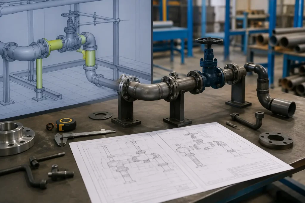
Pipe fabrication accuracy comes down to how well the drawing matches what actually needs to happen in the field. Spool drawings improve that match in several practical ways.
- Accurate pipe dimensions: Because spool drawings come from a modeled system rather than a field measurement, cut lengths reflect the real routing, offsets included. The fabricator cuts to a dimension that already accounts for the pipe’s actual path.
- Correct fitting placement: Elbows, tees, and reducers are shown in the orientation they need to be installed. A fitting rotated even slightly can throw off an entire downstream connection.
- Better control of weld locations: Drawings mark where field welds versus shop welds should occur, keeping welding consistent and helping shops sequence their work efficiently.
- Reduced measurement errors: Manual field measurements introduce human error. When dimensions come from a coordinated model instead, that variable is largely removed.
- Consistent fabrication information: Every spool follows the same format and level of detail, so shop workers aren’t interpreting sketches differently from one drawing to the next.
- Better material identification: Material grade, schedule, and specification are called out clearly, reducing the risk of the wrong pipe or fitting getting welded into the system.
- Improved prefabrication: Because spools are dimensionally accurate, more of the system can be built in a controlled shop environment instead of piece by piece on-site.
- Fewer field modifications: When a spool arrives and fits the way it was drawn, crews aren’t cutting, re-welding, or re-routing pipe in the field — less time, less waste, fewer surprises at inspection.
The Role of BIM Modeling in Spool Drawing Creation
None of this works without accurate BIM modeling behind it. The 3D model is where pipe routing, sizing, slope, and clearances are first established, and it’s the source of every dimension that eventually shows up on a spool drawing.
The flow looks like this: a 3D BIM model is developed, coordinated with other trades, spool drawings are generated from that geometry, fabrication follows, then installation. Each step depends on the last — an inaccurate model carries its errors straight through to a pipe that doesn’t fit.
Why BIM Coordination Matters Before Fabrication
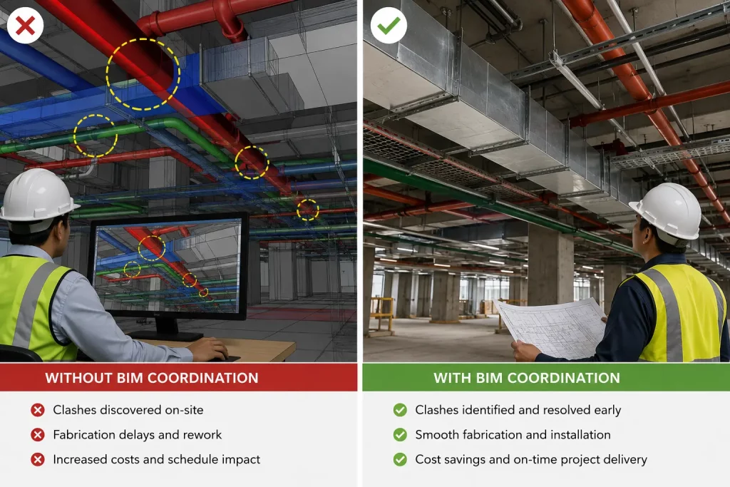
Pipe sharing is done with HVAC ductwork, cable trays, structural members, fire protection, and plumbing in ceiling and mechanical rooms. Piping sent to fabricate without looking at these other systems will result in problems in the field and not in computer modeling.
This is where BIM coordination earns its keep. Clash detection compares the piping model against ductwork, structural, fire protection, and plumbing models to catch conflicts before anything is cut. It’s far cheaper to shift a route three inches in the model than to discover mid-installation it runs into a beam. Coordination also confirms the routing is actually installable, with clearance for insulation, supports, and maintenance access.
Spool Drawings in BIM and Construction Workflows
Spool drawings are one of the clearest points where BIM and construction meet — the model becomes fabrication-ready documentation a shop and field crew rely on daily.
Take the mechanical room where there is the requirement of installing chilled water piping, hot water piping, and condensate piping around chillers, pumps, and air handling units in limited space. Plan this pipework in the model, and the spool drawings automatically get generated keeping in mind limited spaces. Spools arrive pre-built to fit that space, instead of crews working out conflicts with pipe already in hand.
How BIM Services Support Accurate Pipe Fabrication
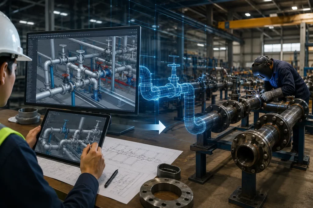
Getting from design intent to a usable spool drawing takes more than software. Experienced BIM services teams support this workflow across model development, clash coordination, fabrication-level detailing, spool drawing preparation, and material identification.
The value is judgment as much as modeling skill — knowing how a fabricator likes spools broken up, or where a coordination issue tends to hide, comes from experience with actual pipe fabrication, not just software. That’s what turns a correct model into a drawing a shop can build from without back-and-forth.
Conclusion
A spool drawing looks like a routine fabrication document, but it’s the output of everything that happened earlier: accurate BIM modeling, thorough BIM coordination, and careful attention to how systems fit together in real space. When that groundwork is solid, spool drawings give fabricators and field crews information they can trust — which is what pipe fabrication accuracy comes down to.
Fewer field modifications, less rework, and smoother installations aren’t the result of luck. They’re the result of a coordinated model translated correctly into a drawing that matches what actually needs to be built.