Picture this: your team just wrapped up clash coordination in a mechanical room, the model looks clean, and everyone’s feeling good. Then the fabricator asks for spool drawings, and someone on the call says, “Wait, don’t we already have shop drawings for that?” It’s a fair question, and it comes up on almost every MEPF project at some point.
While they seem similar, shop drawings and spool drawings are used in the same context and come from the same model. However, they are different deliverables, and confusing them will only waste time in the fabrication area. It is now time to take a closer look at their purpose and difference, as well as situations where both are needed.
What Are Shop Drawings?
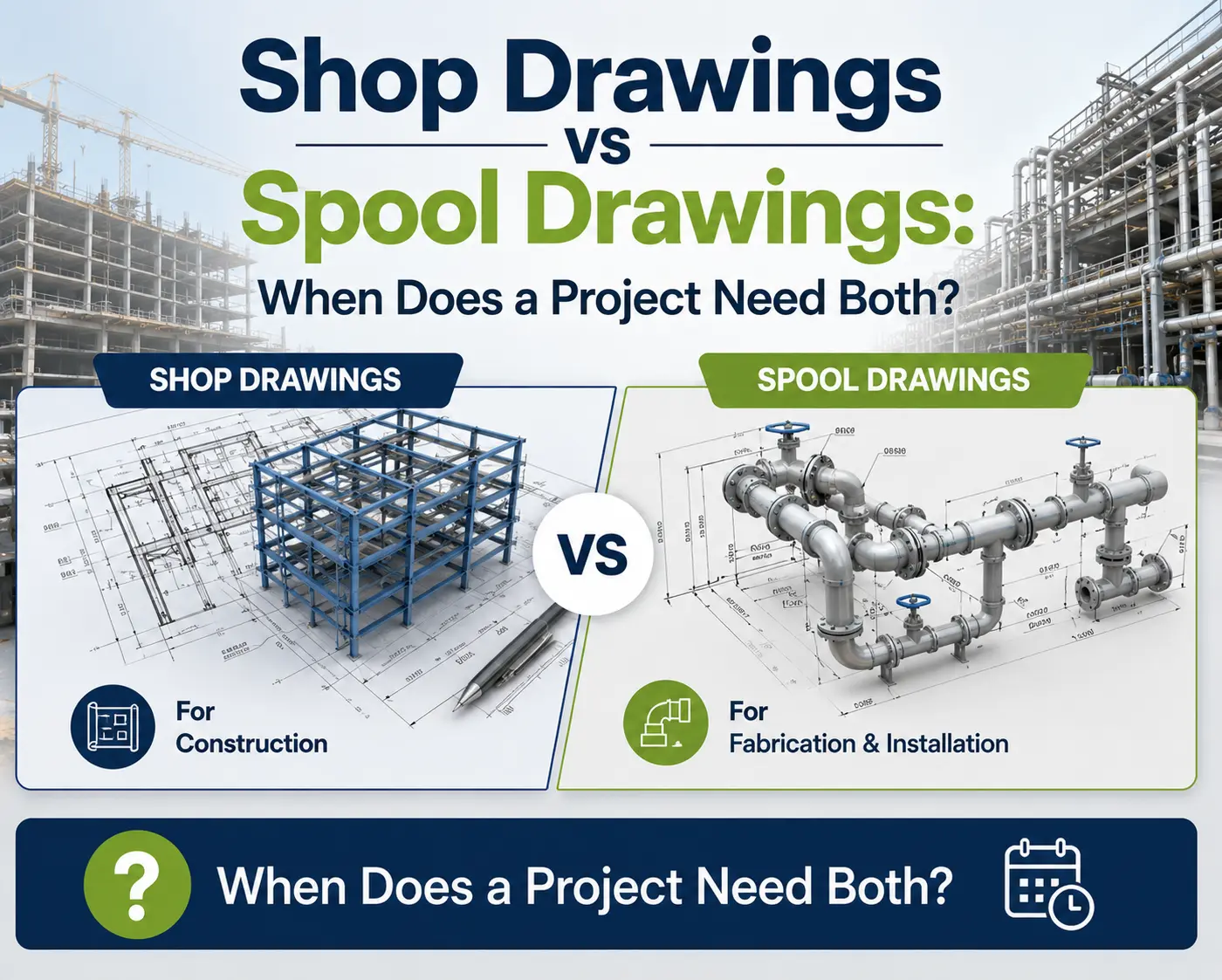
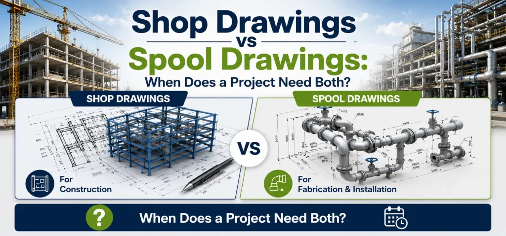
Shop drawings convert the design intent into something that is constructible by the working crew. While architectural or engineering drawings illustrate the design intent, shop drawings illustrate the actual routings, sizes, and coordination involved for the installation of systems without any clashes.
Shop drawings in construction typically include:
- Dimensions and elevations
- Equipment locations
- Pipe and duct routing
- Fittings and connections
- Sections and details
- Penetrations and sleeves
- Hangers and supports
- Installation clearances
Imagine shop drawings as the “how it all goes together” drawings. If you use them from an integrated BIM model rather than producing independent drawings, they are much more consistent because every dimension is drawn from the same 3D model that has already been clash-tested.
Also Read: Why Contractors Need Shop Drawings First
What Are Spool Drawings?
A spool drawing zooms in much further. It focuses on one manageable, fabricable piece of a larger piping or ductwork run, small enough to build in a shop, ship to site, and connect without a crane operator sweating over tolerances.
Where shop drawings show the big picture, a spool drawing hands the fabricator exact instructions for one component. Common information includes:
- Pipe dimensions and cut lengths
- Fittings, elbows, and reducers
- Flanges and valves
- Weld locations
- Material specifications
- Component and spool identification numbers
- Assembly orientation and connection points
While the shop drawings give you information about the route of the pipe, a spool drawing will inform the shop about how the pipe should be cut, welded, and marked before it even exits the fabrication yard. The teams that provide spool drawing services always create these drawings directly from the coordinated model.
Shop Drawings vs Spool Drawings: What’s the Difference?
| Factor | Shop Drawings | Spool Drawings |
| Primary purpose | Installation and coordination guidance | Fabrication and assembly instructions |
| Main users | Installers, contractors, GCs, inspectors | Fabricators, pipe shops, welders |
| Level of detail | System-wide, routing-focused | Component-level, cut-and-weld precision |
| Typical application | Coordinated systems across trades | Individual pipe or duct sections |
| Fabrication use | Limited | Primary purpose |
| Installation use | Primary purpose | Supports final assembly on site |
| System coverage | Broad — full runs or floors | Narrow — one spool at a time |
| Relationship with BIM | Derived from coordinated model | Derived from detailed, spooled model segments |
| Typical output | 2D plans, sections, details | Isometric spool sheets with cut lists |
The table tells part of the story, but here’s the practical version: a shop drawing might show an entire chilled water riser running through four floors, while the spool drawings for that same riser could be a dozen separate sheets, each one representing a section short enough to fit on a truck.
When Does a Project Need Both?
On complex MEPF work, shop drawings and spool drawings usually aren’t competing options — they’re sequential stages of the same workflow. A typical path looks like this:

Design/BIM Model → Coordination → Shop Drawings → Detailed Fabrication Information → Spool Drawings → Fabrication → Installation
Say you’re routing a large plumbing riser through a hospital core. Coordination resolves conflicts with structure and ductwork early on. Shop drawings then get issued so the install crew understands where the riser sits relative to walls, floors, and equipment. From there, the same coordinated geometry gets broken into spools, and spool drawings get generated so the pipe shop can fabricate each section off-site with confidence.
Shop drawings answer “where and how does this get installed.” Spool drawings answer “how does this specific piece get built.” A project with meaningful off-site fabrication almost always needs both.
When Are Shop Drawings Enough?
Not every job needs spool-level detail. Shop drawings alone are often sufficient on:
- Smaller renovation or tenant-improvement projects
- Straightforward, low-complexity installations
- Systems assembled largely on site rather than prefabricated
- Projects with minimal off-site fabrication requirements
- Trades where standard fittings are field-cut as work progresses
If the scope doesn’t call for shop-built assemblies, spool drawings add cost and time without much payoff. The right call really depends on how much of the install happens in the field versus off-site, and that’s a fabrication-strategy decision, not a fixed rule.
When Are Spool Drawings Necessary?
Spool drawings earn their place on projects with real prefabrication volume:
- Large-scale piping systems
- Modular or off-site construction strategies
- Repetitive MEP assemblies across floors
- Data centers, hospitals, and industrial facilities
- Large commercial buildings with tight schedules
Pipe Spool Drawing contains all the information required by the shop to make the item correctly prior to its arrival at the site, and that’s really important when there is little space or time available for on-site modification. In a wider perspective, the pipe spool fabrication drawings serve many other purposes including installation on site.
Also Read: Improving Prefabrication Accuracy with Spool Drawings
How BIM Connects Shop Drawings and Spool Drawings
BIM is really the thread tying both deliverables together. A typical workflow looks like:
- Build the 3D BIM model
- Coordinate MEPF systems across trades
- Detect and resolve clashes
- Validate routes, dimensions, and clearances
- Prepare shop drawings
- Break suitable systems into fabrication-ready spools
- Generate spool drawings
- Fabricate components off-site
- Install and assemble on site
Every step downstream depends on how clean the model is upstream. If clash coordination was rushed, that inaccuracy carries straight through to the spool sheet a fabricator is cutting pipe from. Many contractors now bring in dedicated bim shop drawing services specifically to keep that handoff between coordination, shop drawings, and spool drawings tight and error-free, rather than trying to manage it piecemeal across separate teams.
Other teams will actually pull a bill of materials directly from that spooled model, ensuring that procurement and fabrication are working with the same amount of materials instead of reconciling them afterwards.
Key Benefits of Using Both
- Better coordination between trades before fabrication starts
- Fewer fabrication errors caught only after material is cut
- Reduced field modifications and rework
- Improved installation accuracy on tight schedules
- More reliable material planning and ordering
- Easier, faster fabrication with clear cut lists
- Better communication between BIM teams, fabricators, and installers
- Tighter project scheduling with fewer surprises
- Greater consistency between the model and what actually shows up on site
Conclusion
Shop drawings and spool drawings aren’t interchangeable, and they’re not really competitors either. Shop drawings explain how systems get installed across a building, while spool drawings provide the fabrication-level detail needed to build and assemble specific sections accurately. Whether a project needs one or both really comes down to scope, trade, contract requirements, and how much of the work is happening off-site versus in the field. On complex MEPF projects with real prefabrication volume, using both — built from the same coordinated model — is usually what keeps fabrication errors, rework, and material waste from piling up before the first pipe ever reaches the jobsite.